Quote:
Originally Posted by daygobaker

PWM...is basicallly a signal that turns on and off?
|
Pulse Width Modulation. Yeah, it's a repeated sequence of measured on and off switching. Each off/on cycle always adds up to the same length of time, but the off and on sections of each cycle can proportionately change in length.
Here's a graphic I put together a month or two ago showing PWM as used with light dimmers:

The up part of each wave represents time where the lamp would be lit, while during the down part it would be off. A constantly down line would be the lamp completely switched off, while a constantly up line would be the light at full power.
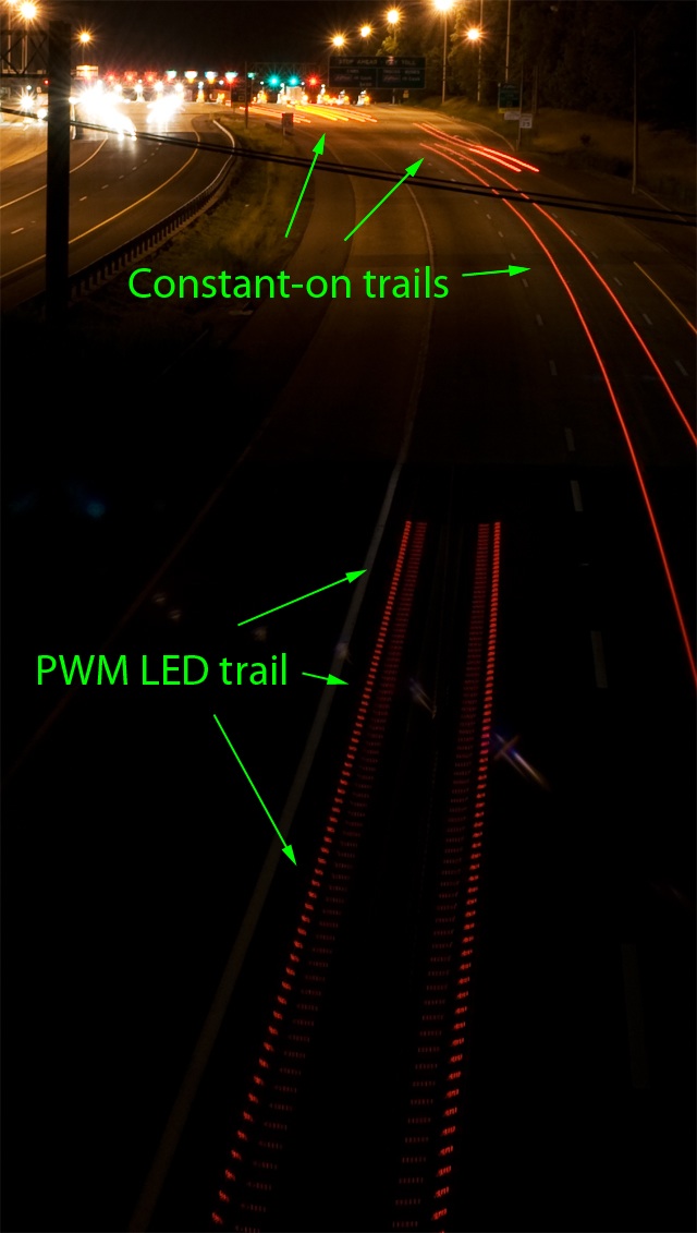
PWM is often used to dim LED lights, such as those found in some modern tail lamps:

With lighting, the switching happens fast enough that the human eye can't normally perceive it, though fast movement such as waving your hand around under the light source can have a freeze-frame strobe-like effect.
Quote:
Originally Posted by daygobaker

what kind of signal are we talking about....volts?...my bad i dont really understand electronics....
|
You can think of electricity like water in a garden hose. Voltage is a measure of the pressure in the hose, while amperage (amps or current) is a measure of how much water is flowing past a point in the hose. The real life counterpart of the hose is a wire, while the water would be electrons. Just like the water in the hose, you need voltage (pressure) to move electrons (the water). This movement can be measured as current (amps).
The final important measurement to know is resistance, measured in ohms (generally represented by the greek letter omega, which looks like a horseshoe). Resistance, as its name suggests, is a measure of an electrical component's (a resistor, solenoid coil or whatever) resistance to the flow of current. Using the water-in-a-hose analogy, a high resistance device would be like stepping on, or putting a kink in the hose. Water flows past, but it's speed (current) is restricted.
Increasing the pressure (voltage) can force more water past the restriction, increasing the current. Similarly, reducing the restriction (resistance) can increase the current. This relationship is known as ohms law. It's stated simply as V (voltage, measured in volts) = I (current, measured in amps) * R (resistance, measured in ohms). If you know, or can measure any two of those values, you can find the third.
Quote:
Originally Posted by daygobaker

basically im worried about frying my ecu...i wanted too know if the signal on the accords and too strong for the ecu....
|
But anyway, in your case, the voltage is pretty much fixed at around 12 volts... Typical for a car electrical system. What you need to look out for is the resistance of the frequency solenoid coil. If the resistance is lower than a VX solenoid, the current that will be allowed to flow through it could damage the ECU component that switches the coil on and off. This is the same principal behind "shorting out" a component... If you make it's resistance zero, or near zero, the flow of current will be limited only by the wire, or what ever else happens to be on the same electrical circuit. Further, this is why fuses are rated in amps.